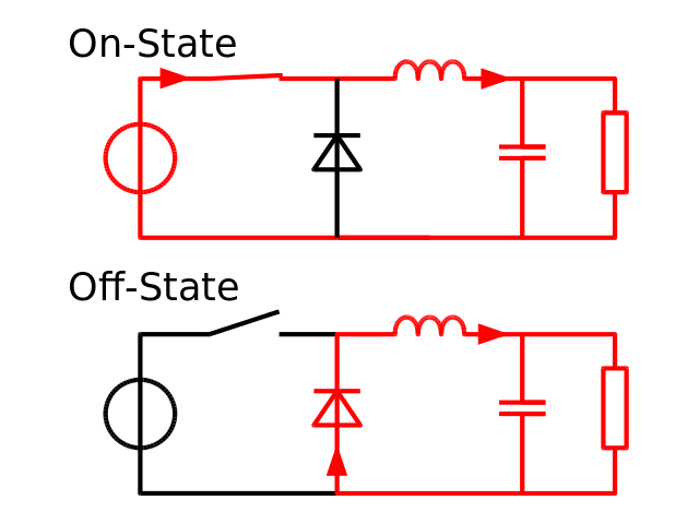
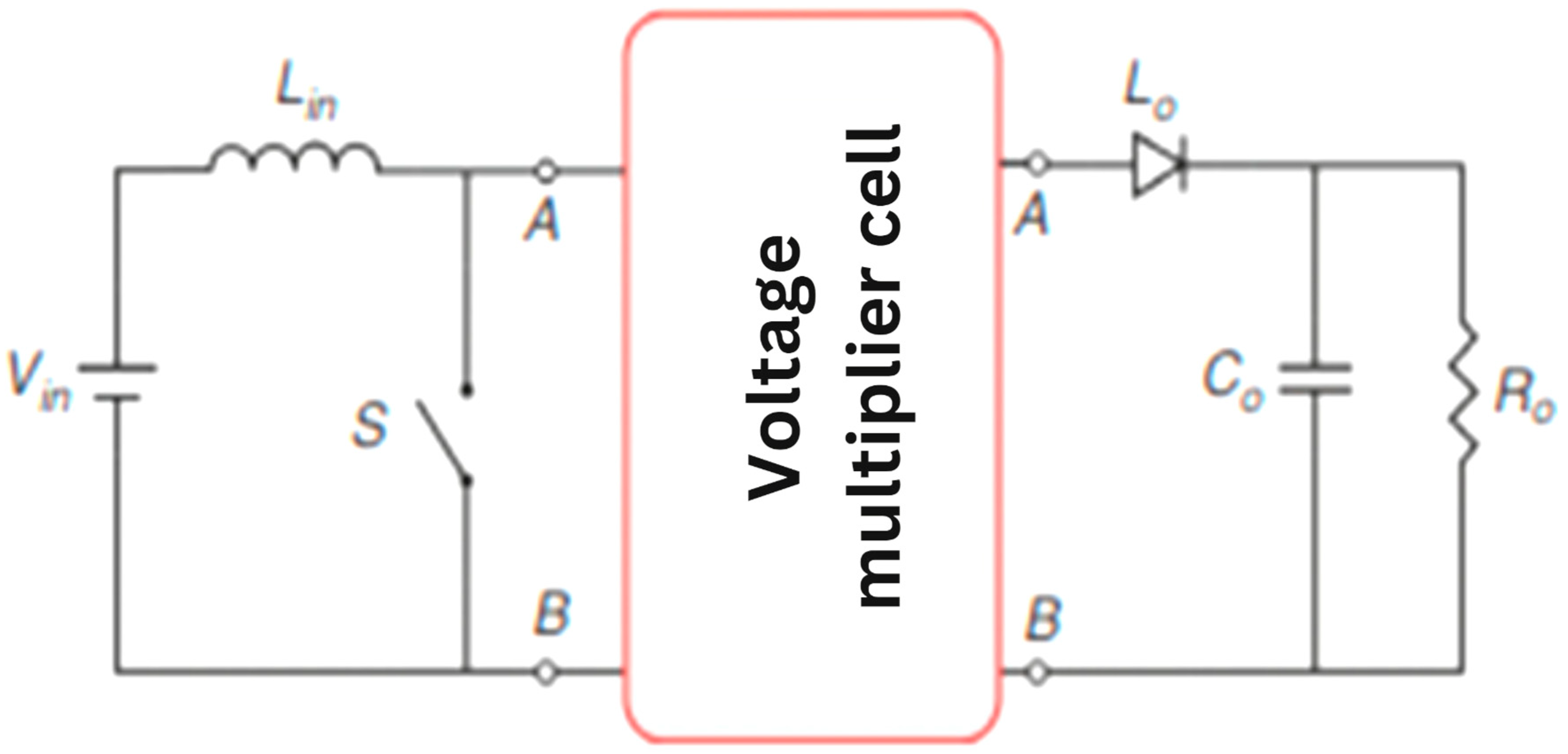
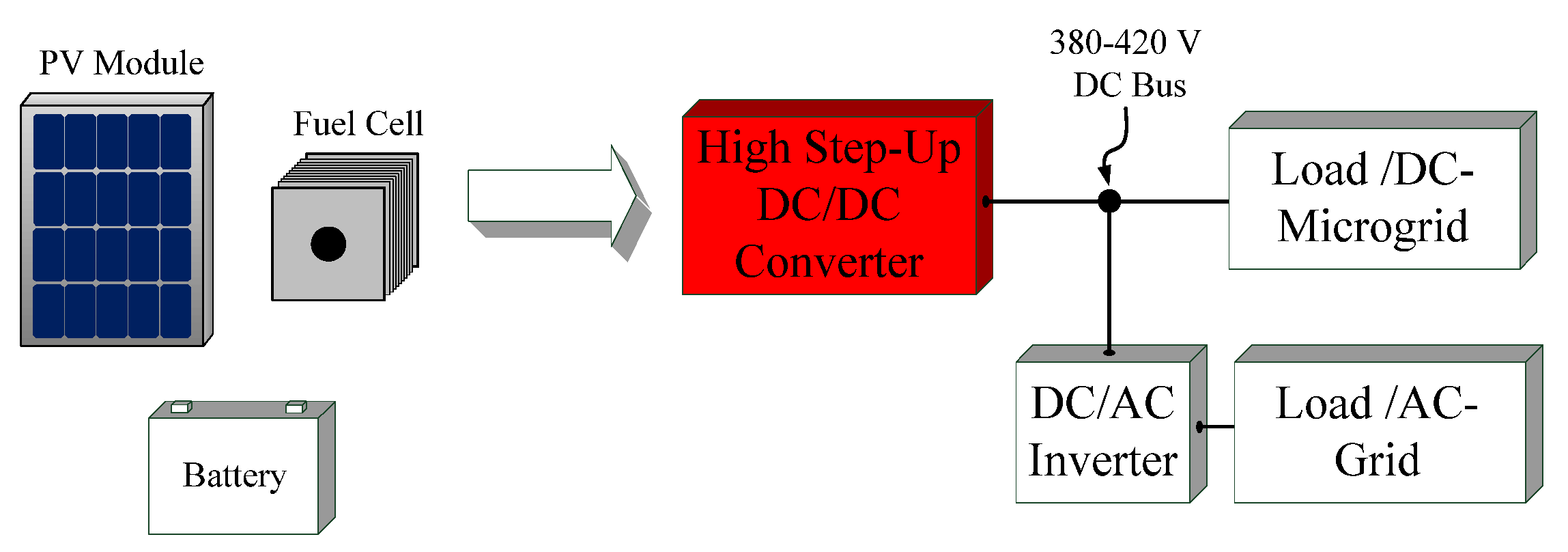
Schematic diagram of a basic Step-Up converter integrated in a
Download scientific diagram | Schematic diagram of a basic Step-Up converter integrated in a photovoltaic generator. PV is a photovoltaic panel, PWM is the Pulse Width Modulator. C1, C2, Rp, Rs, L1, D1 and M1 are the discrete elements constituting the electronic circuit (see the text). from publication: Basic MOSFET Based vs Couple-coils Boost Converters for Photovoltaic Generators | Considering the optimization of a photovoltaic system, several studies show the advantage in the choice of a distributed structure. For such structures small power converters such as the boosts and buck converters appear as most appropriate. We have analysed the efficiency of | MOSFET, Photovoltaics and Boost | ResearchGate, the professional network for scientists.
Comparing a Step Down Converter vs Voltage Regulator - Free Online
4 Easy Boost Converter Circuits Explained - Homemade Circuit Projects
Simple Buck-Boost Converter Circuits Explained - Homemade Circuit
Technologies, Free Full-Text

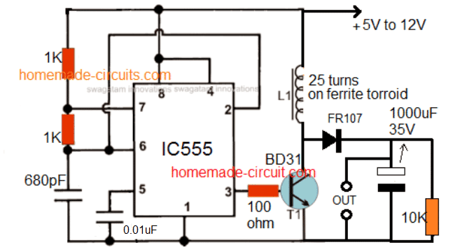
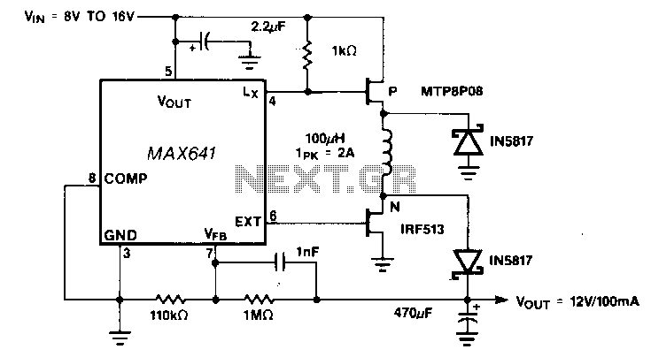
A Simple DC-DC Boost Converter Circuit using 555 Timer IC

Designing a Step-Up DC-to-DC Boost Converter : 7 Steps - Instructables
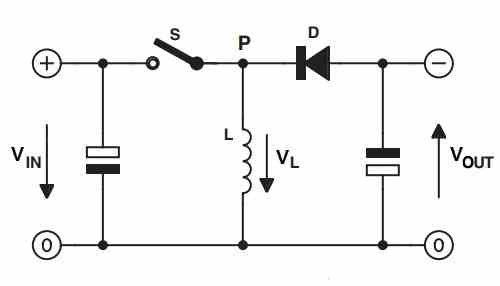
Step-up-down-dc-dc-converter under AC-DC & DC-DC Circuits -13223
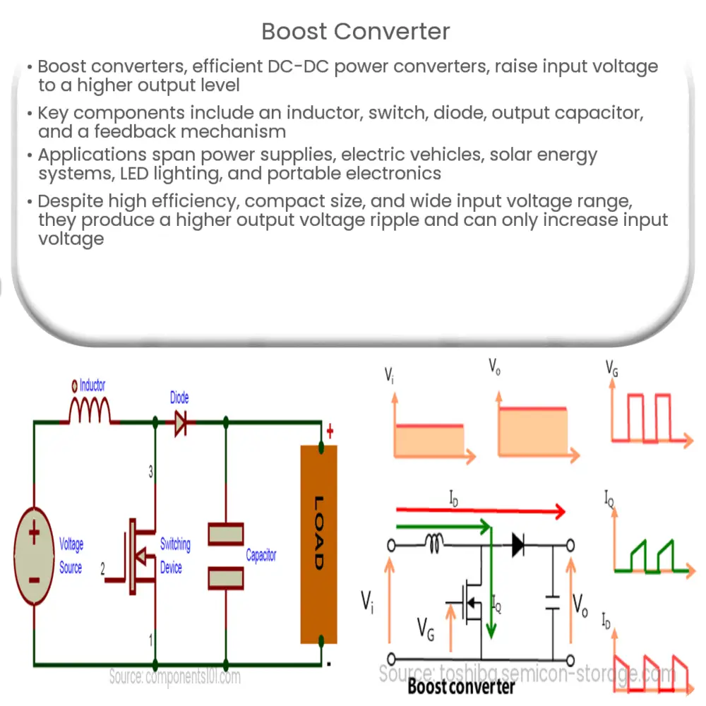
Boost converter How it works, Application & Advantages
Energies, Free Full-Text
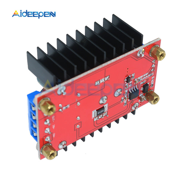
40V-30A Adjustable Switching Power Supply

Boost converter - Wikipedia